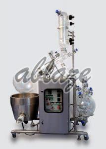
| Business Type | Manufacturer, Exporter, Supplier |
| Color | Grey |
| Automatic Grade | Automatic |
| Area | Upto 50 m2 |
| Click to view more | |
Product Details
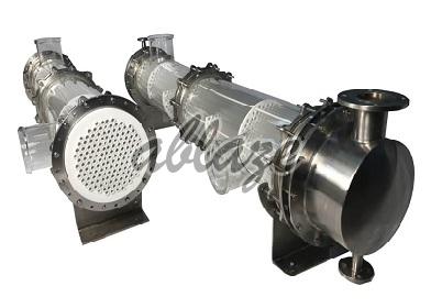
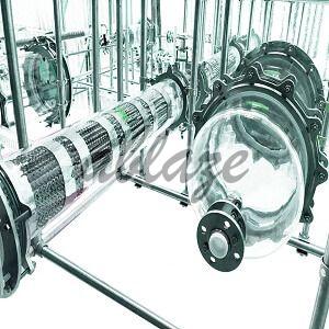
Shell and Tube Heat Exchangers are one of the most common and versatile types of exchangers used in heat transfer applications. They allow transfer of large amounts of heat in a more compact construction than is possible with conventional coil type heat exchangers. Shell and Tube type Heat Exchangers find application as heaters, coolers, condensers, vaporizers, reboilers, etc.
Pertinent Features of Shell Tube Heat Exchanger
- They have colossal Heat Transfer Surfaces.
- They have high Heat Transfer Coefficients.
- The sides of Shell, as well as Tubes, can be made diffusion and corrosion-resistant.
- Their Modular Design helps make the maintenance simple and also makes the reserves part stocking work efficiently.
- They can handle pressure up to +6 bar G.
- They are perfectly suitable for Pharmaceutical GMP applications that manufacture ultra-pure products.
- They are available with a different working capacity of heat transfer areas ranging from 0.3m2 to 50m2.
- They are highly resistant to corrosion, erosion, and oxidation across the full range of operating temperatures.
Variants
- Translucent reinforced protective coating to prevent from accidents from breakage of glass
- Multi-Pass headers in Metal for more efficient heat transfer
- Vertical installation possible with minor modifications
- GMP, cleanroom models available in all types
- Tubes of exotic materials such as Hastelloy etc. available on request in the same design
- Other process connection sizes can be modified as per application and user requirement
- Tubes of SiC and graphite also available, offering higher thermal conductivity.
Types of Shell And Heat Tube Exchangers
TYPE-I: Both Sides Corrosion Resistant
This is the universal and most common design of shell and tube heat exchanger, where both shell side and tube side are resistant to corrosion. It finds usage in applications such as condensation in the shell side, heat recovery, and cooling in a shell or tubes. With minor modifications, it can also be used as a falling film absorber and falling film evaporator.
TYPE-II: Shell Side Corrosion Resistant
Type-II Heat exchangers are very similar to TypesI but have Metal (Mild steel or Stainless Steel) Headers instead of glass headers. These are used in applications where there is no risk of corrosion at the service/utility side. The process side comes in contact only with the glass shell or PTFE components, and hence can be corrosive. Thus, this design 1’5 generally used for condensation and tempering of corrosive liquids.
TYPE-III: Tube Side Corrosion Resistant
Type-II Heat exchangers are very similar to Type-I but have Metal (Mild steel or Stainless Steel) Headers instead of glass headers. These are used in applications where there is no risk of corrosion at the service/utility side. The process side comes in contact only with the glass shell or PTFE components! And hence can be corrosive. Thus, this design is generally used For condensation and tempering 0f corrosive liquids.
TYPE-IV: Shell Side Corrosion Resistant, High Tube Side Pressure!
A key factor due to which maximum permissible pressure is limited in Shell & Tube Heat Exchangers is the Tube sheet, which cannot withstand a high pressure since it is made of pure PTFE. In applications where corrosion is not an issue at the utility side, a reinforcing plate can be installed at the header side of the PTFE Tube Sheet. This increases the maximum pressure limit up to 6 Bar.
TYPE-V: Tube Side Corrosion Resistant; High Shell Side Pressure!
This design of the Shell and Tube Heat exchanger again uses the reinforcing metal plate to increase maximum permissible operating pressure. However, in this type, the pressure is raised on the shell side since the plate is installed on the shell side of the Tube Sheet and not the header side.
Diagram 1
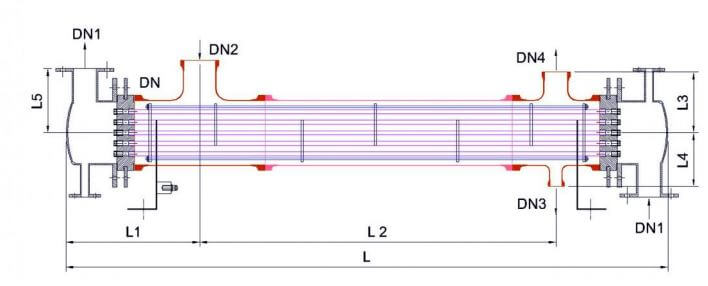
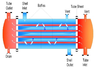
Diagram 2
Mode Of Construction
| OMPONENT | |||||
| SHELL | HEADER | TUBES | |||
| Material | Pressure + barg | Material | Pressure + barg | Material | Pressure + barg |
| Glass | 1(2) | Glass | 1(2) | Glass | 3.5(6) |
| Mild Steel | 6 | Mild Steel | 6 | Silicon Carbide | 3.5(10) |
| Stainless Steel | 6 | Stainless Steel | 6 | Graphite | 3.5(6) |
| Enamel Lined | 6 | Enamel Lined | 6 | - | - |
| PTFE Lined | 6 | PTFE Lined | 6 | - | - |
Technical specification
| SR.No. | Area M2 | DN(Shell Dia) | DN 1(Unity Inlet) | DN 2(Vapour Inlet) | DN 3(Liquid Drain) | DN 4(Vent) | L | L1 | L2 | L3 | L4 | L5 |
| 1 | 0.6 | 100 | 40 | 50 | 25 | 50 | 1150 | 340 | 255 | 125 | 110 | 135 |
| 2 | 1 | 100 | 40 | 50 | 25 | 50 | 1665 | 340 | 770 | 125 | 110 | 135 |
| 3 | 1.5 | 100 | 40 | 80 | 25 | 50 | 2365 | 365 | 1145 | 125 | 110 | 135 |
| 4 | 2.5 | 150 | 50 | 100 | 25 | 50 | 2065 | 375 | 1115 | 150 | 150 | 185 |
| 5 | 3 | 150 | 50 | 100 | 25 | 50 | 2365 | 375 | 1415 | 150 | 150 | 185 |
| 6 | 4 | 150 | 50 | 100 | 25 | 50 | 2965 | 375 | 2015 | 150 | 150 | 185 |
| 7 | 5 | 150 | 50 | 100 | 25 | 50 | 3665 | 375 | 2715 | 150 | 150 | 185 |
| 8 | 5 | 225 | 80 | 150 | 40 | 80 | 2065 | 460 | 985 | 210 | 180 | 220 |
| 9 | 6.3 | 225 | 80 | 150 | 40 | 80 | 2365 | 460 | 1285 | 210 | 185 | 220 |
| 10 | 8 | 225 | 80 | 150 | 40 | 80 | 2965 | 460 | 1885 | 210 | 185 | 220 |
| 11 | 10 | 225 | 80 | 150 | 40 | 80 | 3665 | 460 | 2585 | 210 | 185 | 220 |
| 12 | 10 | 300 | 80 | 225 | 50 | 100 | 2065 | 550 | 815 | 275 | 230 | 270 |
| 13 | 12.5 | 300 | 80 | 225 | 50 | 100 | 2365 | 550 | 1115 | 275 | 230 | 270 |
| 14 | 16 | 300 | 80 | 225 | 50 | 100 | 2965 | 550 | 1715 | 275 | 230 | 270 |
| 15 | 20 | 300 | 80 | 225 | 50 | 100 | 3665 | 550 | 2415 | 275 | 230 | 270 |
| 16 | 25 | 300 | 80 | 225 | 50 | 100 | 4365 | 550 | 3115 | 275 | 230 | 270 |
| 17 | 35 | 400 | 100 | 225 | 50 | 150 | 3415 | 700 | 1865 | 350 | 275 | 325 |
| 18 | 40 | 400 | 100 | 225 | 50 | 150 | 3715 | 700 | 2165 | 350 | 275 | 325 |
| 19 | 40 | 450 | 100 | 225 | 50 | 150 | 3015 | 700 | 1415 | 380 | 300 | 325 |
| 20 | 45 | 400 | 100 | 225 | 50 | 150 | 4415 | 700 | 2865 | 350 | 275 | 325 |
| 21 | 45 | 450 | 100 | 225 | 50 | 150 | 3415 | 700 | 1815 | 380 | 300 | 325 |
| 22 | 50 | 400 | 100 | 225 | 50 | 150 | 4415 | 700 | 2865 | 350 | 275 | 325 |
| 23 | 50 | 450 | 100 | 225 | 50 | 150 | 3715 | 700 | 2215 | 380 | 300 | 325 |

